![]()
![]()
![]()
![]()
![]()
|
|
|
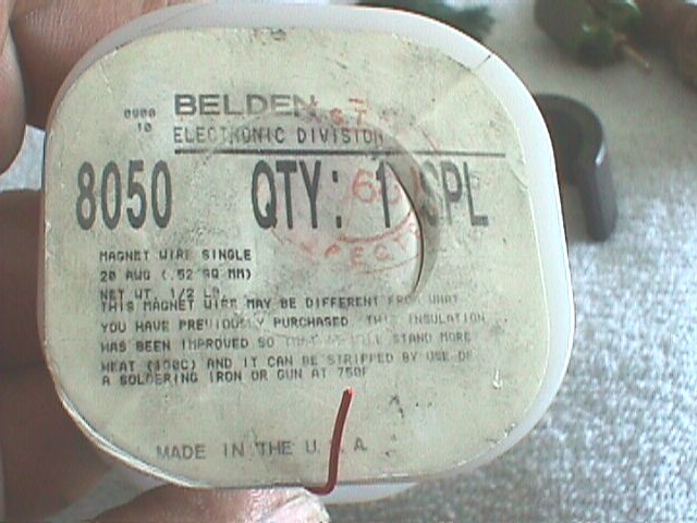
I use lots of different wire. Some times I will reuse the wire on a motor. My best armatures are always done with fresh new wire. (This motor did not have enough wire to re-use!) The wire I will be using for this project is shown in the picture below. It was purchased from Radio Shack by special order. This wire is 20 gauge and is a good mid range wire. Makes great 16, 17, 18 turn single wind motors. It will make a dynamite 9 turn double. The most wire you can get on an armature without sticking out and rubbing the magnets makes the most powerful motor. The rpm's vary but it is the power that is important. If you have more power but less rpm's you can easily increase your pinion a tooth or two and blow'em away. It is the power that counts!
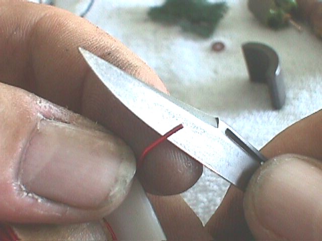
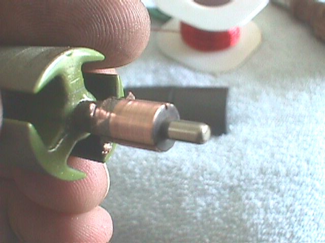
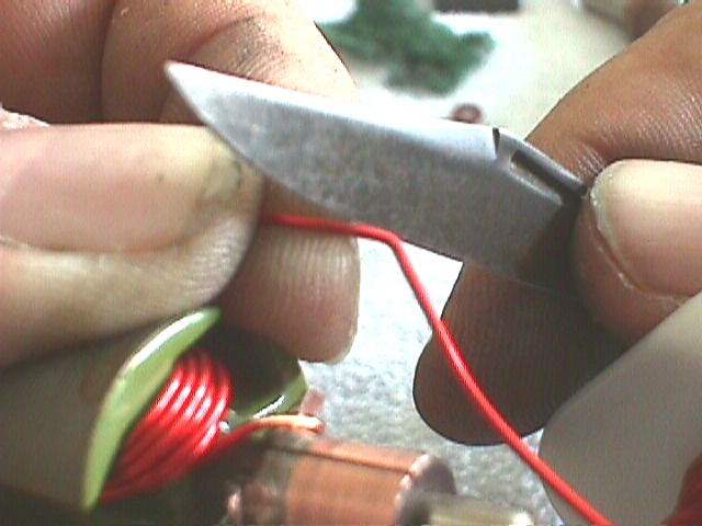
To begin we strip the coating off approximately the first 3/8" of the wire to connect it to the commutator.
We bend a hook in the bared wire to hook it over one of the tabs on the commutator.
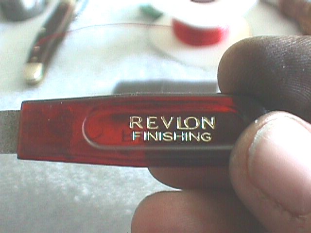
It helps to have the proper tools. In this case I have chosen my wife's diamond chip fingernail file to use as a tool to create a copper mating surface on the commutator for the wire.
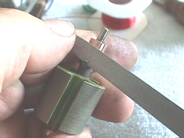
Use the fingernail file (or appropriate substitute if your wife is not as understanding as mine!) to polish the surfaces that will touch the wire both on the tab and the commutator plate.
Here is an example of what the prepared commutator should look like.
Hook the wire over the strongest tab (in your opinion) to begin winding the motor.
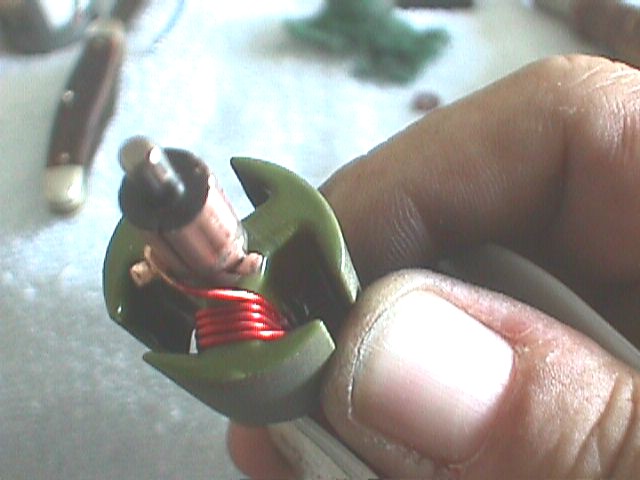
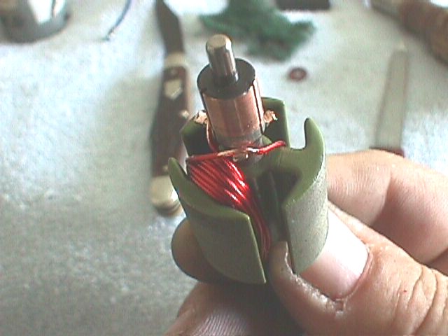
Start winding the wire as shown. Here we have completed 4 turns. Notice how uniform the winding is. Try to duplicate that. This is physically demanding work. Keep your winds as tight as possible at all times.
This armature is being wound to 16 turns. This makes a strong motor and it does not pull too much current that would overheat the funky brushes in the stock end bell. This gauge of wire fills the armature nicely with wire as well. Remember, the more mass of windings the more power.
Each time you finish an arm of the armature clean the coating off the wire that will be looped over or around the next tab. Be careful only to strip just the coating for the area that will be touching the tab. Trimming too much could cause your wire to short out causing run away heat build up and poor performance.
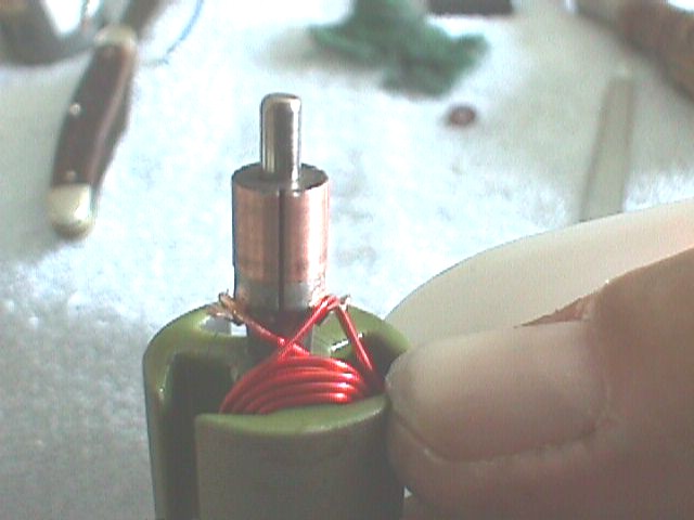
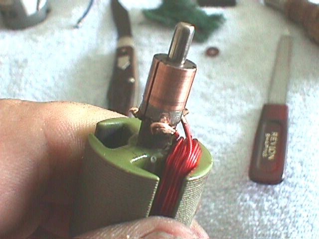
Here is the armature with the first arm wound and the wire stripped and looped over the next post.
Here is another view of the wire stripped and looped over the next post. This is an opportunity to rest the fingers in between each arm. This is a good idea as you must keep the wraps tight and this can be very demanding on the hands.
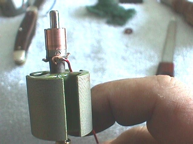
Here is the arm with all three arms wound. Notice the dramatic increase in the amount of wire on this armature as compared to the original winds. Clip the wire off after hooking it over the first tab. This tab will have two wires hooked to it where the other tabs only have the wire looped over them.
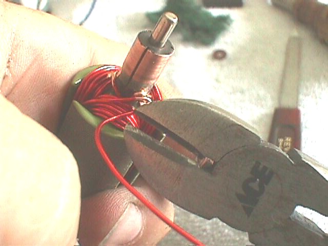
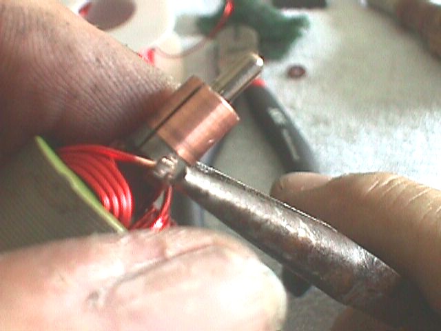
Use a pair of needle nosed pliers to refold the tabs back over the wire and clamp hard to squeeze them down on the wire. Because of the way we have wound this the clamped connections will work very well and there is no need to solder them. Soldering the tabs does not work anyway. The solder will get hot and melt when the motor is run hard and the Commutator plates will not take a higher heat. (Unless you had a custom made spot welder like they do in the factory.) This technique works very well. I have been using it for years and I have motors that have ran till they completely wore out with the tabs crimped.
|
|
|